Vortex Flow Meters in Power Generation: High-Temperature Steam Measurement with Temperature & Pressure Compensation
DATE: 2026.9.14 AUTHOR: Power & Energy Instrumentation Team VIEWS: 3,600+ Vortex Flow Meter Steam Measurement Power Generation Temperature Compensation Pressure Compensation Energy Efficiency
How vortex flow meters with integrated temperature and pressure compensation deliver accurate steam mass flow measurement for power plants, improving energy efficiency and process control
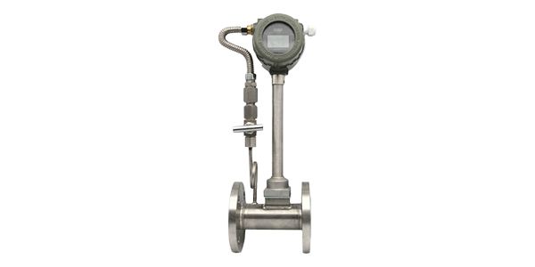
Steam is the lifeblood of power generation. Whether in conventional thermal plants, combined cycle facilities, or industrial cogeneration systems, accurate steam flow measurement is essential for optimizing efficiency, allocating costs, and ensuring safe operation. Vortex flow meters have become the instrument of choice for steam measurement due to their reliability, wide turndown ratio, and ability to handle high temperatures and pressures. When combined with temperature and pressure compensation, vortex flow meters provide accurate mass flow measurement — the true measure of energy transferred.
1. How Vortex Flow Meters Work
1.1 The Vortex Shedding Principle
Vortex flow meters operate on the principle of vortex shedding, first described by Theodore von Kármán:
-
A bluff body (shedder bar) is placed in the flow stream
-
As fluid flows past the bluff body, alternating vortices are shed from each side
-
The frequency of vortex shedding is directly proportional to flow velocity
-
A sensor (piezoelectric, capacitive, or thermal) detects the vortex frequency
-
Flow rate is calculated from the frequency and the meter's K-factor
Key Equation: f = St × V / d
Where: f = vortex frequency, St = Strouhal number (~0.2), V = flow velocity, d = bluff body width
1.2 Advantages for Steam Measurement
|
Advantage
|
Description
|
|
Wide turndown ratio
|
Typically 10:1 to 30:1, handling varying steam loads
|
|
No moving parts
|
No wear, low maintenance, long service life
|
|
High temperature capability
|
Withstands steam up to 400°C+ with proper materials
|
|
High pressure capability
|
Rated for pressures up to 100 bar+
|
|
Low pressure drop
|
Minimal energy loss compared to orifice plates
|
|
Accuracy
|
±1% of reading for liquids, ±1.5% for gases/steam
|
2. Why Temperature & Pressure Compensation is Essential
2.1 The Challenge with Steam
Steam is a compressible fluid whose density varies significantly with temperature and pressure. A vortex flow meter measures volumetric flow (m³/h), but energy content and process control require mass flow (kg/h) or energy flow (GJ/h). Without compensation, errors can be 10-30% or more.
2.2 Compensation Formula
Mass Flow (kg/h) = Volumetric Flow (m³/h) × Density (kg/m³)

Density is calculated from:
- Temperature (T)
- Pressure (P)
- Steam tables or equations of state

For superheated steam:
ρ = f(P, T)

For saturated steam:
ρ = f(P) or f(T) — both are related
Example of Error Without Compensation: A vortex meter calibrated for 10 bar saturated steam (density 5.64 kg/m³) is used at 20 bar. The actual density is 10.05 kg/m³ — an error of 78% if uncompensated. This underscores the importance of real-time compensation.
3. Temperature & Pressure Compensation System Architecture
3.1 System Components
-
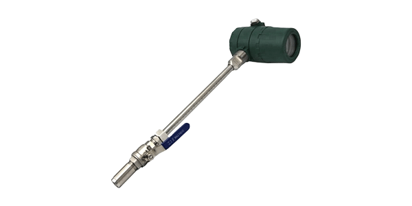
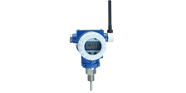
Vortex Flow Meter: Measures volumetric flow (frequency output)
-
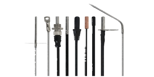
Temperature Sensor: RTD (Pt100) or thermocouple installed downstream
-
Pressure Transmitter: Installed upstream or downstream
-
Flow Computer / Controller: Calculates density and mass flow using steam tables
-
Output: 4-20mA, Modbus, or HART for integration with DCS/SCADA
3.2 Integration Options
|
Option
|
Description
|
Best For
|
|
Integrated Multivariable Meter
|
Vortex meter with built-in T & P sensors and flow computer
|
New installations, compact footprint
|
|
Separate Components
|
Vortex meter + separate T & P transmitters + flow computer
|
Retrofits, flexibility
|
|
DCS-Based Compensation
|
Signals sent to DCS where compensation is calculated
|
Existing DCS infrastructure
|
4. Steam Flow Measurement Applications in Power Plants
Boiler Feedwater
Feedwater Flow Measurement
-
Measure feedwater flow to boilers
-
Typically high pressure (100-250 bar), high temperature (200-300°C)
-
Vortex meters with high-pressure ratings
-
Compensation for density changes
Main Steam
Main Steam Flow
-
Measure steam from boiler to turbine
-
High temperature (540-600°C) and pressure (150-250 bar)
-
Critical for efficiency calculation (heat rate)
-
Requires high-temperature materials and compensation
Reheat Steam
Reheat Steam Flow
-
Measure steam returning from reheater to turbine
-
High temperature (540-600°C), moderate pressure
-
Essential for turbine efficiency monitoring
Auxiliary Steam
Auxiliary Steam Flow
-
Measure steam for auxiliary equipment (feedwater pumps, air preheaters)
-
Lower pressure and temperature
-
Important for plant auxiliary power calculation
Condensate
Condensate Flow
-
Measure condensate return from condenser
-
Lower temperature (30-60°C), low pressure
-
Useful for water balance and efficiency calculations
Steam Distribution
Steam Distribution & Custody Transfer
-
Measure steam delivered to industrial customers
-
Requires high accuracy for billing
-
Compensation essential for fair billing
5. Compensation Calculation Example
Given:
- Vortex flow meter measures volumetric flow: Qv = 500 m³/h
- Steam pressure: P = 10 bar (absolute)
- Steam temperature: T = 250°C (superheated)

Step 1: Determine steam density from steam tables
At 10 bar, 250°C: ρ = 4.13 kg/m³

Step 2: Calculate mass flow
Mass Flow (Qm) = Qv × ρ
Qm = 500 m³/h × 4.13 kg/m³
Qm = 2,065 kg/h

Step 3: Calculate energy flow (optional)
Enthalpy (h) at 10 bar, 250°C: h = 2,950 kJ/kg
Energy Flow = Qm × h = 2,065 kg/h × 2,950 kJ/kg
Energy Flow = 6,091,750 kJ/h = 6,092 MJ/h = 6.09 GJ/h

If uncompensated (assuming density 4.0 kg/m³):
Qm = 500 × 4.0 = 2,000 kg/h → 3.2% error
6. Installation Best Practices
6.1 Location Requirements
-
Straight pipe runs: Minimum 10-20 pipe diameters upstream, 5 pipe diameters downstream
-
Avoid obstructions: Install away from valves, elbows, reducers, and other fittings
-
Orientation: For steam, install in horizontal or vertical upward flow lines
-
Accessibility: Ensure adequate space for maintenance and sensor replacement
6.2 Sensor Placement for Compensation
-
Temperature sensor: Install 3-5 pipe diameters downstream of vortex meter
-
Pressure transmitter: Install 3-5 pipe diameters upstream or downstream
-
Insulation: Insulate temperature sensor and piping to prevent heat loss
-
Condensate pots: Use for pressure transmitter connections on steam lines
6.3 Materials & Ratings
|
Application
|
Temperature
|
Pressure
|
Recommended Materials
|
|
Main Steam
|
540-600°C
|
150-250 bar
|
316SS, Alloy 625, P91
|
|
Reheat Steam
|
540-600°C
|
50-100 bar
|
316SS, Alloy 625
|
|
Auxiliary Steam
|
200-300°C
|
10-30 bar
|
316SS
|
|
Condensate
|
30-60°C
|
5-20 bar
|
316SS, carbon steel
|
7. Advantages & Limitations
Advantages
Why Choose Vortex Flow Meters
-
No moving parts — high reliability
-
Wide turndown ratio
-
Low pressure drop — energy savings
-
High temperature/pressure capability
-
Accuracy unaffected by fluid properties (within limits)
-
Easy integration with DCS/SCADA
-
Lower installation cost than orifice plates
Limitations
Considerations
-
Requires minimum Reynolds number (turbulent flow)
-
Not suitable for very low flow rates
-
Limited to clean fluids (not for slurries)
-
Vibration can affect measurement
-
Requires straight pipe runs for accuracy
-
Compensation requires accurate steam tables
8. Energy Efficiency & Economic Benefits
|
Benefit
|
Typical Improvement
|
Annual Value (300 MW Plant)
|
|
Heat rate improvement
|
0.5-1.0%
|
$500,000 - $1,000,000
|
|
Steam loss reduction
|
1-3%
|
$200,000 - $600,000
|
|
Maintenance cost reduction
|
20-40% (vs. orifice plates)
|
$50,000 - $150,000
|
|
Energy billing accuracy
|
2-5% improvement
|
$100,000 - $500,000
|
ROI Example: A 300 MW power plant invests $150,000 in vortex flow meters with T&P compensation for main steam and reheat steam measurement. Annual savings: heat rate improvement ($750,000), maintenance reduction ($80,000), billing accuracy ($200,000). Total annual benefit: $1,030,000. Payback period: ~2 months. 5-year ROI: 3,300%.
9. Case Studies
Case 1: 600 MW Coal-Fired Power Plant — Heat Rate Optimization
A 600 MW coal-fired power plant replaced aging orifice plate flow meters on main steam and reheat steam lines with vortex flow meters featuring integrated temperature and pressure compensation. The new meters provided accurate mass flow measurement with ±1% accuracy, compared to ±2-3% for the orifice plates. The improved accuracy allowed the plant to optimize boiler and turbine operations, achieving a 0.8% improvement in heat rate — saving over $1.2 million annually in fuel costs.
Case 2: Combined Cycle Plant — Steam Custody Transfer
A combined cycle power plant selling steam to a neighboring industrial facility installed vortex flow meters with compensation for custody transfer. The meters provided accurate mass flow and energy flow measurement, ensuring fair billing and reducing disputes. The system included redundant sensors and data logging for audit trail and billing verification.
Case 3: Industrial Cogeneration — Auxiliary Steam Monitoring
An industrial cogeneration plant used vortex flow meters with T&P compensation to monitor steam usage across various plant areas (feedwater heating, air preheating, process heating). The data identified areas of high steam consumption and enabled the plant to optimize steam distribution, reducing overall steam usage by 8% and saving $350,000 annually.
10. Frequently Asked Questions
Q1: Why is temperature and pressure compensation necessary for steam flow measurement?
A: Steam density varies significantly with temperature and pressure. Without compensation, volumetric flow readings cannot be accurately converted to mass flow, leading to errors of 10-30% or more.
Q2: What is the typical accuracy of a vortex flow meter with compensation?
A: ±1-1.5% of reading for mass flow, including the uncertainty of the compensation inputs (typically ±0.5°C for temperature, ±0.1% for pressure).
Q3: Can vortex flow meters handle superheated steam?
A: Yes, with appropriate materials and temperature ratings. Vortex meters are available for steam temperatures up to 400°C or higher, depending on the model and materials.
Q4: What is the minimum Reynolds number for accurate vortex flow measurement?
A: Typically 10,000 or higher to ensure turbulent flow and stable vortex shedding. Below this, accuracy may degrade.
Q5: How often should vortex flow meters be calibrated?
A: Typically every 2-3 years, or as recommended by the manufacturer. Calibration can be performed in-situ or in a flow laboratory. Compensation sensors (T & P) should be calibrated annually.
11. Conclusion: Accurate Steam Measurement for Power Generation
Key Takeaways:
-
Vortex flow meters with temperature and pressure compensation provide accurate steam mass flow measurement
-
Compensation is essential because steam density varies with temperature and pressure
-
Applications include main steam, reheat steam, feedwater, auxiliary steam, and custody transfer
-
Proper installation (straight runs, sensor placement) is critical for accuracy
-
Accurate steam measurement delivers significant energy savings and ROI for power plants
Vortex flow meters with temperature and pressure compensation are essential tools for power generation. They provide the accurate mass flow data needed for heat rate optimization, energy billing, and process control. With payback periods often measured in months, investing in accurate steam measurement is one of the most cost-effective improvements a power plant can make.