


Always disconnect power before performing any repairs. Use appropriate personal protective equipment (PPE). If unsure about any procedure, consult the manufacturer or a qualified technician.
Common Turbidity Sensor Faults
Turbidity sensors can develop various issues affecting measurement accuracy and reliability. Early detection and proper diagnosis are crucial for maintaining optimal performance.
Follow this systematic approach to identify sensor issues:
- Visual Inspection: Check for physical damage, fouling, or contamination
- Error Code Analysis: Review system error codes and warnings
- Signal Verification: Test electrical connections and signal integrity
- Calibration Check: Verify calibration status and accuracy
- Performance Testing: Compare readings against known standards
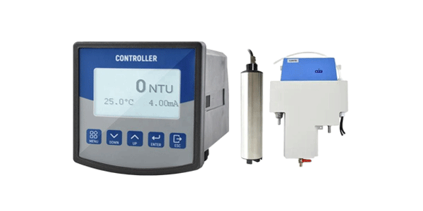
Zero Readings/No Output
Sensor shows 0 NTU regardless of sample turbidity. Often caused by complete optical path obstruction or power failure.
Drifting Readings
Gradual changes in readings without actual sample changes. Typically indicates contamination buildup or component aging.
Erratic Measurements
Unstable readings jumping between values. Often related to electrical interference or loose connections.
Bubble Interference
Air bubbles causing false high readings. Common in improperly degassed samples or turbulent flow conditions.
Error Code Reference Table
| Error Code | Description | Likely Cause | Severity |
|---|---|---|---|
| E-101 | Optical Path Blocked | Window fouling, debris accumulation | High |
| E-102 | Light Source Failure | LED/Laser malfunction, power issue | High |
| E-103 | Detector Signal Low | Detector aging, contamination | Medium |
| E-104 | Temperature Error | Compensation circuit failure | Medium |
| E-105 | Calibration Error | Invalid calibration data | Medium |
Step-by-Step Repair Procedures
Before disassembling any sensor, ensure you have the manufacturer's service manual. Some sensors contain optical components that require specific alignment procedures.
Cleaning Optical Windows
Gently clean optical surfaces using manufacturer-approved cleaning solutions. Use lint-free wipes and avoid abrasive materials that could scratch optical surfaces.
Replacing Light Source
For LED-based sensors, follow specific procedures for LED replacement including proper alignment and power adjustment. Record original LED specifications.
Seal Replacement
Replace all O-rings and seals during maintenance. Use compatible materials and lubricate properly with sensor-grade lubricants.
Calibration & Verification
Always use fresh calibration standards. Record calibration dates, standard lot numbers, and environmental conditions. Perform verification after calibration using a different standard.
Post-Repair Verification Protocol
Zero Check
Verify sensor reads 0.00 ±0.02 NTU in ultrapure water after proper degassing.
Span Verification
Check calibration using at least two different standard concentrations.
Linearity Test
Test multiple points across measurement range to ensure linear response.
Preventive Maintenance Schedule
- Daily: Visual inspection, zero check verification
- Weekly: Optical window cleaning, calibration check
- Monthly: Complete cleaning, O-ring inspection
- Quarterly: Full calibration, electrical testing
- Annually: Complete overhaul, component replacement
Need Professional Sensor Support?
Contact our certified sensor technicians for expert repair services, spare parts, and technical consultations.
Get Technical Support