Clip-On PT1000 Surface Sensor for HVAC & Refrigeration Copper Pipes
Pipe Temperature Feedback Without Opening the Refrigerant Circuit
An immersion probe needs a brazed boss in the copper line — which means recovering the charge, evacuating, leak testing and recharging. On a commissioned split system, a heat pump or a packaged rooftop unit, nobody wants that for a single temperature point. This sensor clips onto the outside of a Ø9–10 mm copper tube instead: a grooved copper probe seated against the pipe wall, held by a removable copper clip, with a PT1000 Class A element and a 3-wire lead back to the controller. It fits in the space between the coil and the service panel, and it comes off again when the valve underneath needs attention.
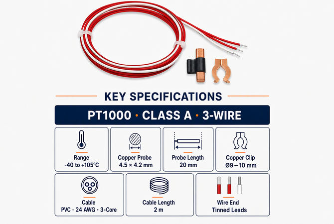
PT1000
Class A · 3-wire A/A/B
-40~105 °C
measuring range
Ø9–10 mm
copper clip tube size
4.5 × 4.2
mm grooved copper probe
2 m
PVC 24 AWG 3-core lead
In one line — a removable clip-on PT1000 pipe-surface sensor that gives an HVAC controller, PLC or BMS direct copper-pipe temperature feedback on suction lines, liquid lines and heat exchanger piping, with no brazing, no drilling and no system shutdown.
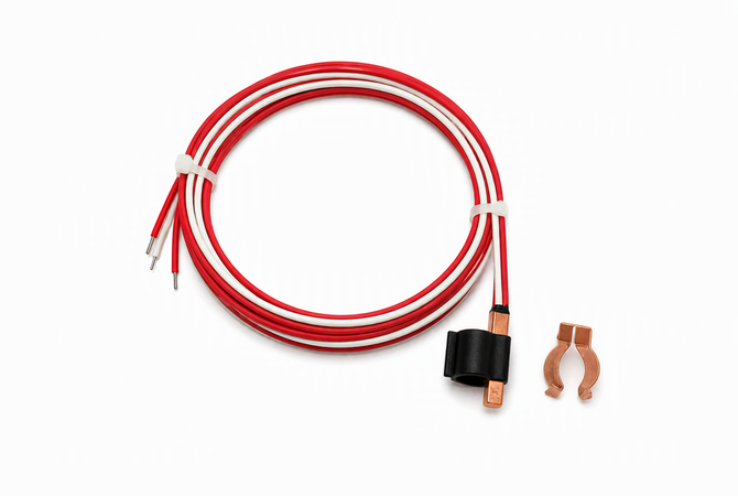
Standard supply: grooved copper probe, removable Ø9–10 mm copper clip, black retaining sleeve, 2 m PVC 24 AWG 3-core cable with tinned leads.
Why Clip-On
Three Reasons a Refrigeration Line Is Never Tapped for a Sensor
01
Opening the circuit costs more than the instrument
A brazed thermowell on a charged line means recovery, nitrogen purge, brazing, pressure test, evacuation and recharge — plus the risk of a leak and a warranty question on a sealed system. For a monitoring point, that trade rarely makes sense.
The refrigerant circuit stays sealed and untouched
02
Ø9–10 mm tube leaves no room for a well
Suction and liquid lines in split and heat-pump units are small-bore copper, packed against coils, valves and insulation. A threaded boss simply does not fit — and thin-wall copper should not take one anyway.
A 4.5 × 4.2 mm probe, 20 mm long, sits entirely outside the tube
03
Service access has to survive the installation
Adhesive and cable ties are one-shot: to reach the joint or the valve underneath, the sensor is cut off and replaced. On equipment that is opened for annual service, that becomes a recurring cost.
The copper clip lifts off and refits in seconds, no residue
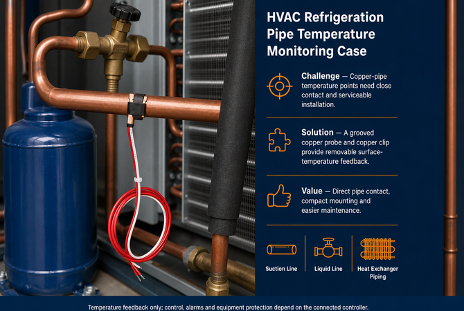
The case in one view: close contact on copper pipe, removable installation, direct pipe-surface feedback — suction line, liquid line and heat exchanger piping. Temperature feedback only; control and alarms depend on the connected controller.
Key Features
Six Choices That Decide Whether the Reading Is Usable
Groove
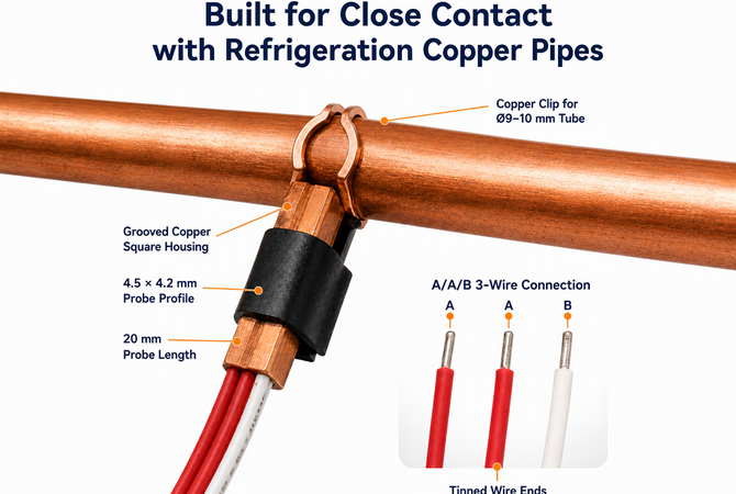
Grooved Copper Square Housing
A 4.5 × 4.2 mm copper profile with a machined groove that matches the tube curvature. Instead of a line contact between a flat pad and a round pipe, the probe sits on a broad metal-to-metal patch — the reason the reading stays repeatable across fitters.
Ø9–10
Removable Copper Clip
A formed copper clip grips Ø9–10 mm refrigeration tube and applies even pressure along the probe. It is a mechanical fit, not an adhesive: lift it off for service and reuse it. Copper also matches the pipe, so there is no galvanic pair at the contact face.
PT1000
PT1000 · Class A
1000 Ω at 0 °C with roughly 3.85 Ω per °C — ten times the signal of a Pt100. Lead resistance becomes far less significant, which is exactly what you want on a 2 m cable routed through a crowded outdoor unit.
A/A/B
3-Wire Connection
Two red A legs and one white B leg let a matched RTD input compensate the lead resistance. The pre-tinned ends land directly in a terminal block with no extra ferrules needed.
20 mm
20 mm Probe Length
Long enough to give the element a stable contact patch, short enough to fit inside the existing pipe insulation and behind a service panel without a stand-off bracket.
2 m
PVC 24 AWG 3-Core, 2 m
A compact three-core lead that routes through trunking and around pipe supports without kinking, with enough length to reach the controller terminal strip in a typical unit. Tinned wire ends, stripped and ready to land.
Key specifications as supplied. The table in Section 10 repeats these values — confirm any deviation against your order before publication.
Build Detail
Built for Close Contact With Refrigeration Copper Pipes
Grooved copper housing · 4.5 × 4.2 mm profile · 20 mm length · Ø9–10 mm copper clip · A/A/B 3-wire · tinned ends.
The Groove and the 20 mm Body
The groove is cut to the tube radius so the copper housing beds onto the pipe rather than balancing on a tangent. The 20 mm length spreads the sensing area along the tube, averaging out local variation instead of reading one hot spot on the wall.
The Black Retaining Sleeve
A short sleeve holds the probe and clip together as one assembly during fitting. It also gives the cable a strain-relief point, so a tug on the 2 m lead does not lever the copper face off the pipe.
A / A / B 3-Wire Leads
Two red conductors on the A side, one white on the B side, all tinned. On a 3-wire RTD input the second A leg measures and cancels the lead resistance; on a 2-wire input, join the two A legs at the terminal and accept the small residual error.
Tinned Wire Ends
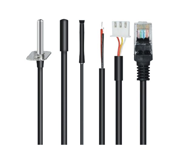
Pre-stripped and tinned so they will not fray in a screw terminal and take solder cleanly if a connector is fitted later. No plug is supplied as standard — the sensor terminates at the controller you already have.
Installation
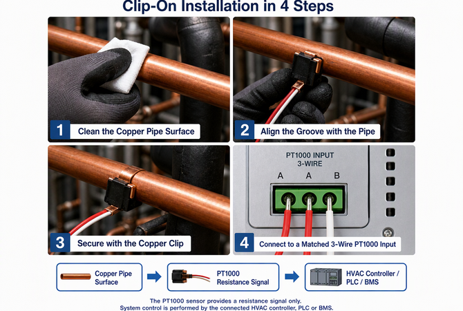
Clip-On in Four Steps — the Fourth One Decides the Reading
Clean the copper · align the groove · secure the clip · connect to a matched 3-wire PT1000 input. System control is performed by the connected HVAC controller, PLC or BMS.
1
Clean the Copper
Wipe the tube to bare, bright copper over a patch slightly longer than the probe. Oxidation, oil and paint flakes are thermal insulators — a 0.1 mm air gap can cost more than the element tolerance.
2
Align the Groove
Seat the grooved face squarely along the tube axis. It should sit flat with no rocking. Do not fit it over a bend, a brazed joint or a weld bead — the groove will bridge and only the edges will touch.
3
Secure the Copper Clip
Press the clip over the Ø9–10 mm tube and probe until it grips. Check the assembly cannot rotate by hand, then reinstate the pipe insulation over it with no air gap — especially on a suction line, where condensation will otherwise form at the joint.
4
Connect to a Matched Input
Land A / A / B on a 3-wire PT1000 input of the HVAC controller, PLC or BMS. Confirm the input type before energising, then compare the displayed value with a reference thermometer at ambient.
The Signal Chain
Copper Pipe Surfacesuction / liquid / exchanger line
→
PT1000 ResistanceClass A · 3-wire A/A/B
→
HVAC ControllerPLC or BMS input
→
Control & Alarmsexecuted by the controller
A PT1000 is not a Pt100, and a 3-wire input is not a 2-wire input. On a Pt100 input this sensor reads roughly a tenth of the expected resistance and the controller will report an implausible temperature or a sensor fault — without any obvious wiring error to find. Check the input configuration for "PT1000" and "3-wire" before commissioning. Section 9 has the comparison table.
Applications
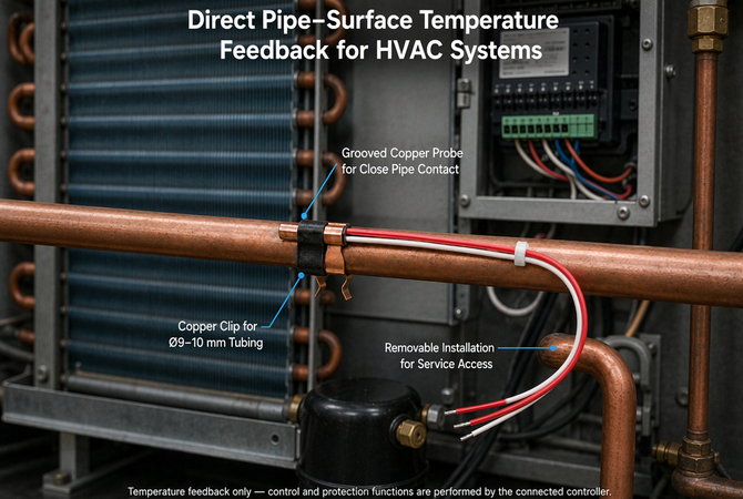
Direct Pipe-Surface Temperature Feedback for HVAC Systems
Grooved probe for close pipe contact · Ø9–10 mm copper clip · removable for service access. Temperature feedback only — control and protection are performed by the connected controller.
Suction Line
Pipe-surface temperature on the low-pressure side for superheat trend monitoring, frost and condensation watch, and commissioning checks. Insulate over the clip after fitting — an exposed suction-line probe reads the ambient air around it, not the line.
Liquid Line
Tracking liquid-line temperature alongside pressure for subcooling calculations and trend logging. The compact 20 mm body fits inside the existing insulation without a bracket or a modification to the pipe run.
Heat Exchanger Piping
Header and distributor tubes on coils and plate exchangers, where a brazed boss is impractical and the space between the fins and the panel is measured in millimetres. One probe per circuit gives a comparable trend across the coil.
Retrofit & Service Points
Adding temperature points to commissioned split systems, heat pumps, rooftop packaged units and chillers without recovering the charge. The clip removes cleanly when a joint, valve or filter drier underneath needs work.
Surface temperature is not refrigerant temperature. This probe reports the copper wall it touches. It is the right instrument for trend monitoring, commissioning, superheat and subcooling trend work and service diagnostics; it is not a substitute for an immersion sensor where a certified fluid value is required. See Section 8 for what to expect in practice.
Scope of Supply
Temperature Feedback Only — This Is Not a Protection Device
Important — read before specifying This sensor is a passive PT1000 resistance element. It outputs a resistance that changes with the temperature of the pipe surface it touches. It does not generate alarms, stop a compressor, trip a high-pressure switch, shut down a unit or make any safety decision. All setpoints, control logic, alarm thresholds, interlocks and equipment protection are defined and executed by the connected HVAC controller, PLC or BMS — and by the system integrator who configured them. The same applies to every figure and application described on this page.
What it does
Report copper-pipe surface temperature as a PT1000 resistance signal; support trend logging, commissioning surveys, service diagnostics and controller temperature inputs on suction, liquid and exchanger lines.
What it does not do
Measure refrigerant temperature directly; replace a certified safety or limit thermostat; act as a high-pressure, freeze or fire protection device; make autonomous control decisions of any kind.
For safety-critical functions — freeze protection, compressor discharge limits, safety cut-outs — use devices qualified to the relevant system standard and follow the equipment manufacturer's protection design. We are glad to supply the monitoring points around that system, but we will not represent this probe as a safety device.
Accuracy Reality
What a Pipe-Surface Reading Actually Tells You
A Class A element is accurate on its own. The measurement is only as good as the thermal path from refrigerant to element — and that path runs through the copper wall, the contact patch, the clip pressure and whatever insulation covers the joint. Here is what to expect in the field.
Site condition
Typical deviation from true fluid temperature
Bare copper, groove fully seated, insulation reinstated, line running
0.5–1.5 °C
Insulated, but oxidised / painted pipe or a loose clip
1–3 °C
Probe left exposed, indoor, still air
3–8 °C
Probe exposed in an outdoor unit, fan airflow or direct sun
8–15 °C or worse
Fitted over a bend, joint or weld bead
Unreliable — part of the face is not touching
System off, static refrigerant in the line
Unreliable — no convective mixing to the wall
Indicative figures for steady-state conditions. Actual deviation depends on tube wall, refrigerant state, flow, insulation quality and ambient conditions. For a certified process value, use an immersion sensor in a thermowell.
The biggest accuracy gain is not in the sensor — it is the insulation you put back over it. An exposed clip-on probe reads a blend of pipe wall and ambient air. On a cold suction line in a warm plant room, it can sit several degrees high and sweat at the joint; cover it properly and the same probe tracks the line closely. If a customer reports "the clip-on reads wrong", check the surface prep and the insulation before blaming the element.
Where clip-on is the right instrument. Trend monitoring, commissioning, service diagnostics, superheat and subcooling trends, and any retrofit where the circuit cannot be opened. Where the number has to stand up in an audit or a certified setpoint, it does not replace an immersion probe — and we will tell you so before you order.
Before You Order
PT1000 Is Not Interchangeable With Pt100 or NTC
"PT1000" describes a specific resistance curve, not a general class of temperature probe. Controller inputs are configured for one element type, and a mismatch produces a plausible-looking but wrong number rather than an obvious fault. Check the input specification first.
Element
R at 0 °C
R at 25 °C
Typical controller input
PT1000 (this sensor)
1000 Ω
≈ 1097 Ω
PT1000 RTD input, HVAC / BMS / PLC
Pt100
100 Ω
≈ 109.7 Ω
Pt100 RTD input, industrial transmitters
NTC 10K B3950
—
10 kΩ
Room thermostats, underfloor heating
NTC 100K B3950
—
100 kΩ
Some BMS and cabinet controllers
Resistance values are nominal per IEC 60751 for platinum RTDs. An NTC curve falls with temperature; a platinum RTD curve rises. They cannot be substituted for one another.
Understanding the A / A / B Leads
Terminal
Conductor
What it does
A (×2)
Two red leads
Both on the same side of the element. The third-wire compensation circuit measures the lead resistance through one of them and subtracts it.
B
One white lead
The return leg. Together with either A leg it forms the measured resistance.
2-wire input
Join A + A
Land the two red leads in the A terminal and the white lead in B. Reading is valid on a 2 m lead, but lead compensation is lost.
One-minute check before commissioning. Look for "PT1000" and "3-wire" in the controller's input configuration, then compare the displayed reading with a reference thermometer at ambient while the unit is off. A curve mismatch or an NTC-configured input will not throw a fault — it will quietly display the wrong temperature all season. If your controller only accepts Pt100 or NTC, tell us the model: other element curves can be built on the same grooved copper body.
Why PT1000 here. At roughly 3.85 Ω/°C, a PT1000 gives ten times the signal of a Pt100 for the same temperature change. The 2 m lead resistance becomes a small fraction of the measured value, and the 3-wire circuit removes most of what remains — a good match for long cable runs through an outdoor unit.
Specifications
Technical Data
Sensor element
PT1000 platinum RTD, Class A
Wiring
3-wire, A / A / B
Measuring range
-40 to +105 °C
Copper probe
Grooved square housing, 4.5 × 4.2 mm profile
Probe length
20 mm
Copper clip
For Ø9–10 mm copper tube, removable
Cable
PVC, 24 AWG, 3-core
Cable length
2 m
Wire end
Tinned leads, pre-stripped
Output signal
Passive PT1000 resistance, no polarity
Mounting
Clip-on to the outside of the copper pipe — no brazing, no drilling, no opening of the refrigerant circuit
Compatible input
HVAC controller / PLC / BMS with a matched 3-wire PT1000 input
Measurement
Pipe-surface temperature, not refrigerant temperature
Function
Temperature feedback only — control, alarms and equipment protection are performed by the connected controller
Values describe the standard configuration shown on the specification sheet. Element class, cable length, clip diameter and termination are confirmed against each order before production.
OEM & Customisation
Built Around Your Tube Size and Your Controller
We build this sensor for HVAC OEMs, refrigeration service companies and instrumentation distributors, so the parts that vary are the ones your installation actually needs.
Element — PT1000 Class A standard; other classes and curves matched to your controller input
Wiring — 3-wire A/A/B standard; 2-wire and 4-wire versions on the same copper body
Cable — 2 m PVC 24 AWG standard; other lengths and jacket materials to order
Clip — Ø9–10 mm standard; other tube diameters and clip profiles for your pipe run
Termination — tinned leads standard; ferrules, JST / Molex housings, M12 or your own connector
Documentation — resistance test report per batch, RoHS / REACH declaration
Trial orders welcome. Send the copper tube outside diameter, the temperature range and the controller model or input type. We will confirm the element curve, clip size and wiring, and build samples before a production run.
FAQ
Questions From HVAC Engineers and Service Teams
Can I connect this sensor to a Pt100 input?
No. A PT1000 is 1000 Ω at 0 °C, ten times a Pt100, and a Pt100-configured input will report an implausible temperature or a sensor fault. The input must be configured for PT1000. If your controller only accepts Pt100 or an NTC curve, tell us the model — we can build a matching version on the same grooved copper body.
What do the A / A / B wires mean?
It is a standard 3-wire RTD connection: two red A leads on one side of the element and one white B lead on the other. A 3-wire controller input uses the extra A leg to measure and cancel lead resistance. On a 2-wire input, land both red leads in A and the white lead in B — the reading stays usable on a 2 m lead, but that compensation is lost.
Does it fit my copper pipe?
The standard clip is formed for Ø9–10 mm refrigeration tube. Measure the outside diameter of the bare tube, not the insulation. Other diameters can be made to order; a clip that is even 1 mm oversize will not hold the probe flat against the wall and the reading will drift.
Does it measure the refrigerant temperature?
No — it measures the copper pipe wall it touches. With the surface cleaned, the groove fully seated and the insulation reinstated, the deviation from true fluid temperature is typically 0.5–1.5 °C. Left exposed to ambient air, the error is several times larger. For a certified fluid value, use an immersion sensor in a thermowell.
Do I have to reinstate the insulation over the sensor?
Yes, for any meaningful accuracy. An exposed probe reads a blend of pipe wall and surrounding air; on a cold suction line it can read high and cause condensation at the joint. Cover the assembly with no air gap — this is the single largest accuracy improvement available, and it also prevents sweating on the low-pressure side.
Can the sensor be removed for service?
Yes — that is the point of the copper clip. Lift it off to reach the joint or valve underneath, then clean the tube and refit it. There is no adhesive residue, no brazed boss and no need to recover the refrigerant charge.
Will it trigger an alarm or protect the compressor?
No. It is a passive PT1000 element that provides temperature feedback only. All setpoints, control logic, alarm thresholds, interlocks and protective actions are performed by the connected HVAC controller, PLC or BMS. It is not a safety device and should not be specified as one.
Can I get a longer cable or a different connector?
Yes. Cable length, jacket material, clip diameter, wiring (2-wire / 4-wire) and terminations including ferrules, JST / Molex housings, M12 or your own connector can be specified. Send the tube diameter and controller model at enquiry stage and we will confirm the build.
Adding pipe temperature points to an HVAC or refrigeration unit?
Send the copper tube outside diameter, the temperature range and your controller model. We will confirm the PT1000 curve, clip size and wiring, quote against your volume and build samples before production.
Have questions? Need a quote? We are ready to help! Fill out the form and a member of our sales team will contact you to discuss your requirements. You can also give us a call at (86)177-9158-1665.