An NTC Sensor Built to Survive the Screed, Not Just the Showroom
A floor sensor gets one chance. It is buried in screed, covered by tile or timber, and from that moment on nobody can reach it again. Every failure — moisture creeping up the cores, alkaline mortar attacking the shell, a cable crushed during pour — is unfixable without breaking the floor. So this sensor is specified for the day it disappears, not the day it ships.
10K B3950
NTC, matches mainstream thermostats
±0.5 °C
accuracy at 25 °C
-30~105 °C
operating range
IP67
sealed probe, mortar-proof
1.5-20 m
cable length to order
In one line — a 10 kΩ B3950 NTC floor probe with an epoxy-potted, fully sealed tip, white PVC jacket rated to 105 °C, and tinned bare-wire terminals, for hydronic and electric underfloor heating, thermostat OEMs and retrofit projects.
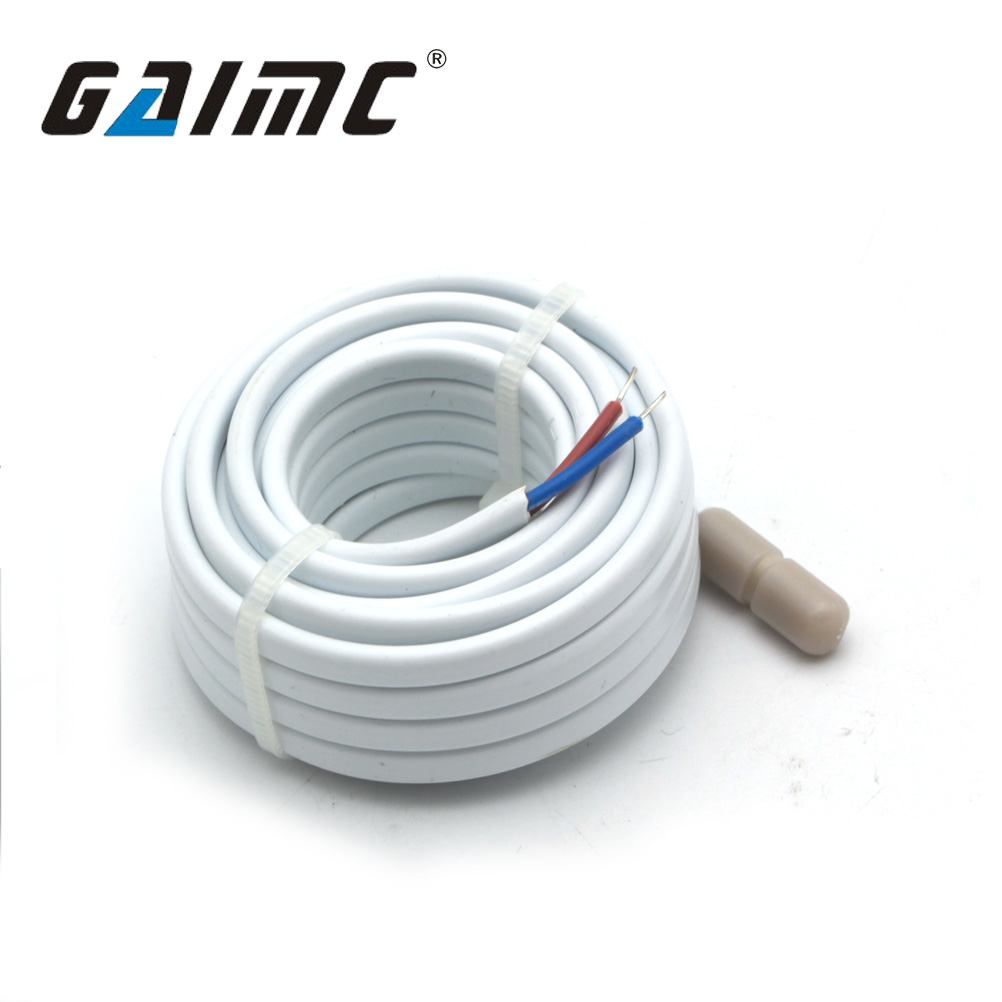
Standard supply: 10K B3950 NTC, sealed probe with protective cap, white PVC cable, red/blue tinned bare-wire terminals.
Why Floor Sensors Fail
Four Ways a Buried Sensor Goes Wrong — and How This One Prevents It
In underfloor heating the sensor is the only component nobody can service. That makes the failure modes worth spelling out.
01
Moisture travels up the cable cores
This is the classic one. Water enters at the terminal end or through a pinhole at the tip, migrates along the conductor by capillary action, and reaches the NTC bead weeks later. The thermostat starts reading 3–8 °C low, the floor overheats, and the fault looks like a thermostat problem.
Fixed by epoxy potting plus a mechanically sealed tip-to-jacket transition
02
Alkaline screed attacks the probe shell
Fresh cement screed sits at pH 12–13 for months. Thin ABS shells go brittle, crack at the seam, and let the alkaline water in — which is exactly when the reading starts to drift.
Fixed by an alkali-resistant shell with a full-length encapsulated body
03
The cable is crushed during pour or walked on
One worker stepping on a cable laid over a pipe, or a wheelbarrow crossing the mat, and the conductor work-hardens. It reads fine on the day of commissioning and fails two winters later.
Fixed by stranded copper cores and a thick-wall PVC jacket
04
The beta value does not match the thermostat
Two 10 kΩ NTCs with different B values read identically at 25 °C and disagree by 1–3 °C at 5 °C or 45 °C. The system "works", the floor is simply never the temperature the display says.
Fixed by supplying the exact B value your thermostat expects — B3950 standard
Key Features
What the Specification Actually Buys You
10K
10K B3950 NTC Element
The most widely matched curve in underfloor heating controls. 10 kΩ at 25 °C, B 3950 K, ±0.5 °C — a direct replacement for the sensor most thermostats were designed around.
IP
Epoxy-Potted Sealed Tip
IP67 sealed probe with a fully encapsulated body. No air pocket, no seam for alkaline water to find, no path along the cores into the element.
PVC
White PVC Jacket, 105 °C
Smooth, flexible and easy to pull through conduit. Rated well above any floor-heating surface temperature, and white so it disappears under light screed and timber.
TIN
Tinned Bare-Wire Terminals
Pre-stripped, pre-tinned red and blue tails. Tinned copper does not oxidise in a damp wall box, and the colour coding removes the guesswork at the thermostat terminals.
τ
Fast, Stable Response
Small thermal mass gives a τ of roughly 10 s in still water — quick enough for floor-limit protection without the reading twitching on every burner cycle.
OEM
Lengths and Curves to Order
1.5 m to 20 m cable, alternative B values and resistance ratings, connector options and your own labelling — built for thermostat brands and distributors.
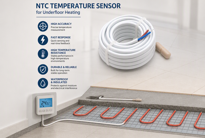
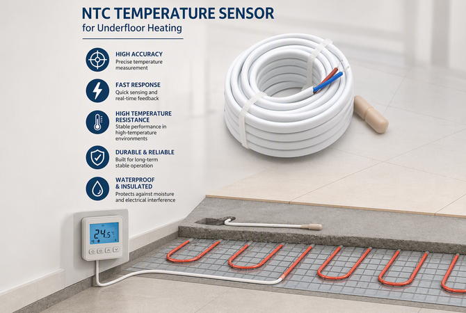
High accuracy · fast response · high temperature resistance · durable construction · waterproof and insulated.
Build Detail
Four Parts, Photographed Close Up
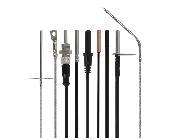
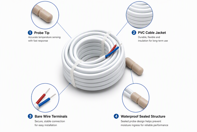
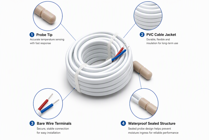
Probe tip · PVC cable jacket · bare wire terminals · waterproof sealed structure.
Probe Tip
Encapsulated NTC bead in a rounded shell, roughly Ø6 mm, with a smooth nose so it slides into a conduit or sits between pipes without snagging. Fast thermal coupling to the screed, no exposed metal to corrode.
PVC Cable Jacket
Thick-wall white PVC over stranded copper. Flexible down to -30 °C for cold-store and unheated-site installation, rated to 105 °C conductor temperature, and smooth enough to pull through 16 mm conduit.
Bare Wire Terminals
Red and blue pre-tinned tails, 10 mm stripped. Tinning stops the copper blackening in a damp wall box and gives a clean clamp under a screw terminal — no ferrule needed on most thermostats.
Waterproof Sealed Structure
Epoxy fill plus a moulded transition between shell and jacket. The seal is mechanical and chemical, not a bead of silicone — which is the difference between IP67 that holds for a season and one that holds for a decade.
Installation
Three Steps, and Two Rules That Decide the Reading
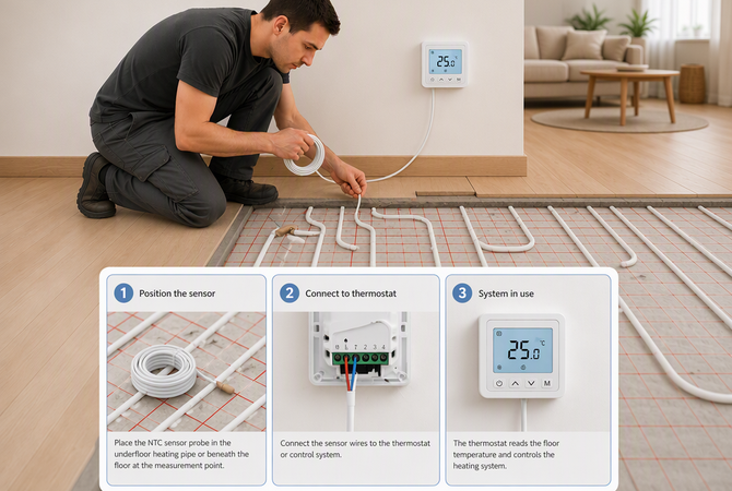
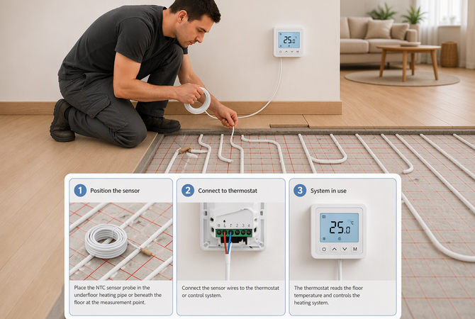
Position the sensor · connect to the thermostat · commission the system.
1
Position the Sensor
Fix the probe between two heating loops, at least 300 mm from the manifold and away from a pipe joint, then let the screed cover it. Where a conduit is used, cap the end and leave the probe free inside it so it can be replaced.
2
Connect to the Thermostat
Land the red and blue tails on the NTC / floor-sensor terminals (usually T1 and T2). NTC elements have no polarity, so either way round reads the same — but keep the pair on one terminal block, not split across two.
3
Commission the System
Set the floor-limit to the screed manufacturer's figure — typically 45–55 °C surface, lower for timber. Read the floor temperature before the first heat-up and compare it with a contact thermometer; a mismatch means the B value is wrong.
Two rules that decide whether the reading is right. First, never coil spare cable inside the screed — a coil becomes a hot spot and the sensor reads the coil, not the floor. Leave the surplus in the wall box. Second, keep the probe at least 300 mm from the manifold and from any pipe coupling, or you will measure the supply water instead of the floor.
Specifications
Technical Data
Sensor type
NTC thermistor, 10 kΩ at 25 °C
Beta value (B25/50)
3950 K standard; 3435 K, 3977 K or customer-specified on request
Bare wire, 10 mm stripped and tinned; red / blue colour coded
Response time
τ0.9 ≈ 10 s in stirred water
Insulation resistance
≥ 100 MΩ at 500 VDC
Dielectric strength
1500 VAC / 1 min, no breakdown
Chemical resistance
Alkali-resistant shell, suitable for direct contact with cement screed
Compliance
RoHS / REACH; optional calibration report per batch
Values describe the standard configuration. Resistance value, B value, cable length and connector are confirmed against each order before production.
Before You Order
10K B3950 Is the Default — Make Sure It Is Yours
Most underfloor heating thermostats are built around a 10 kΩ NTC with a 3950 K beta. But "10 kΩ" alone is not a specification: the resistance curve is defined by the B value, and mismatched curves produce a floor that is quietly 2–3 °C off.
How to confirm in one minute. Look at the thermostat's installation manual or its floor-sensor setting: it will state something like "NTC 10K B3950" or "10 kΩ @ 25 °C, β 3950". If it only says "NTC 10K", ask the manufacturer for the beta — or send us the thermostat model and we will match the curve. If your project uses PT1000 or a 12 kΩ curve, tell us: we build those on the same body.
Why this matters more on a floor than anywhere else. A 2 °C error in a room sensor is a comfort complaint. A 2 °C error in a floor sensor is either an overheated screed or a heating system that never reaches setpoint — and you find out only after the floor covering is down.
Applications
Where This Sensor Is Specified
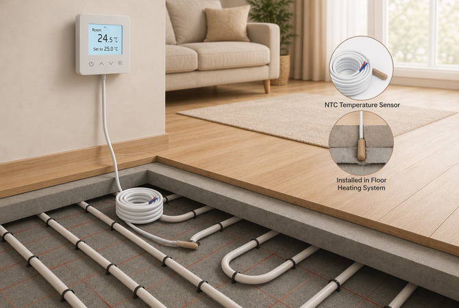
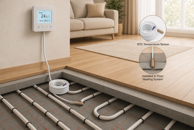
Buried at the measurement point, wired back to the thermostat — the only sensor in the system that cannot be replaced later.
Hydronic Underfloor Heating
Floor-limit sensing in screed or between pipe loops, wired to a manifold-zone thermostat. Keeps surface temperature inside the range the floor covering allows.
Electric Radiant Mats
Laid between heating cable runs and covered by levelling compound. The sealed tip matters here: electric mats run hotter and drive moisture migration faster than a wet system.
Thermostat OEM & Private Label
Supplied to thermostat brands as the sensor in the box — matched curve, matched cable length, your label on the bag and your connector on the end.
Retrofit & Renovation
Pulled through existing conduit to replace a failed sensor without lifting the floor — the reason the probe diameter and jacket smoothness are specified as tightly as they are.
Cable Length
Choose the Length by Route, Not by Room Size
Cable length is set by the distance the cable actually travels — out of the screed, up the wall, across to the thermostat — not by floor area. Measure the route, add 1 m, then pick the next standard length up.
Route length (probe to thermostat)
Order this length
Typical case
Up to 3 m
3 m
Bathroom or single-zone retrofit
3–5 m
5 m
Apartment, thermostat on the same wall
5–10 m
10 m
Living area, thermostat across the room
10–15 m
15 m
Multi-zone floor, riser to the next level
15–20 m
20 m
Villa, long riser, plant-room thermostat
Never leave the surplus coiled in the screed — coil it in the wall box or at the thermostat. A coil buried in concrete reads its own hot spot, not the floor.
OEM & Customisation
Built to Your Thermostat, Not Ours
We supply this sensor to heating-control brands, distributors and underfloor heating contractors, so the variable parts are the ones you actually specify.
Accuracy — ±0.5 °C standard; ±0.2 °C selected batches for calibration-critical work
Cable — 1.5 m to 20 m, white PVC standard, or silicone / PTFE for higher temperature
Termination — bare wire, tinned, ferrule, JST / Molex housing, or your connector
Probe shell — Ø5 / Ø6 mm, rounded or flat tip, with or without protective cap
Branding — printed jacket, labelled bag, barcode and retail packaging
Trial orders welcome. Send the thermostat model or the curve you need, and we will confirm the matching B value and quote against your volume — samples before production.
FAQ
Questions From Contractors and Thermostat Brands
Will this sensor work with my underfloor heating thermostat?
It will if your thermostat specifies a 10 kΩ NTC with a 3950 K beta — the most common floor-sensor curve. Send us the thermostat model and we will confirm the match; if it needs a different B value or resistance, we build that too.
Can it be buried directly in cement screed?
Yes. The shell is alkali-resistant and the body is fully encapsulated, so direct contact with fresh screed is fine. Where local practice calls for a conduit, run the probe inside it with a capped end so the sensor stays replaceable.
Is the probe really waterproof, or just splash-proof?
IP67 with an epoxy-potted body and a moulded shell-to-jacket seal — it is designed for permanent burial in damp screed, not just occasional splashes. The bare terminals at the far end must still be made off inside a dry wall box.
Does it matter which wire goes where?
No. An NTC is a pure resistance, so red and blue can be landed either way round on T1 / T2. What does matter is keeping both on the same terminal pair and not sharing the block with mains wiring.
How accurate is it at floor temperatures?
±0.5 °C at 25 °C, and within about ±1.0 °C across 0–60 °C for a standard B3950 curve. Selected ±0.2 °C batches are available if you are calibrating against a reference thermometer at commissioning.
What is the maximum temperature it can take?
105 °C at the cable and probe — far above any underfloor surface limit, which is normally capped at 45–55 °C. The headroom is there because screed during curing and near-manifold positions can run hotter than the design surface temperature.
Can I get a longer cable or a connector on the end?
Yes. Cable runs to 20 m as standard, longer on request, and we can terminate with ferrules, JST or Molex housings, or your own connector and pinout.
Have questions? Need a quote? We are ready to help! Fill out the form and a member of our sales team will contact you to discuss your requirements. You can also give us a call at (86)177-9158-1665.